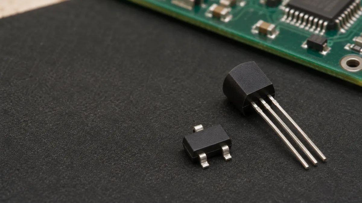
MMBT3904 is an NPN transistor, while MMBT3906 is a PNP transistor. Although both come in a SOT-23 package with identical pinouts (pin 1 base, pin 2 emitter, pin 3 collector), they cannot be swapped directly. Their bias polarities and current directions are opposite. A board wired to forward-bias an NPN will not automatically drive a PNP. The circuit must provide the correct base drive relative to the emitter reference.
The Devices Have Opposite Polarities
The MCC MMBT3904 datasheet, Rev.3-6-08182023, identifies an NPN device. The MCC MMBT3906 datasheet, Rev.4-1-04182023, identifies a PNP device. These are the two manufacturer-specific references for this comparison.
The emitter arrow is the visual cue. It points outward for NPN and inward for PNP. During normal forward operation, conventional collector current flows into the collector for NPN and out of the collector for PNP. These are collector-current directions. Base-drive current is a separate discussion, covered below. (We use conventional current here, not electron flow.)
The StockWake MMBT3904 listing identifies MCC as its manufacturer. That sets the document choice. It does not establish the suitability of a particular offered lot or ordering suffix.
Shared pin numbers don't remove the polarity difference
Both devices come in SOT-23 packages in these MCC documents. Both assign pin 1 to base, pin 2 to emitter, and pin 3 to collector. Matching terminal names do not erase the polarity difference. A board connection intended to forward-bias an NPN does not automatically provide the right drive for a PNP.
Retain the numbered manufacturer drawing when mapping those terminals. Do not add an assumed top-view or bottom-view label to an unlabeled figure. If a printed mark is your starting point, the guide to top markings and complete part numbers covers that separate identification task.
Base Drive Is Referenced to the Emitter
Forward bias uses opposite polarity
The reference is the emitter, not ground by default. With VBE defined as VB – VE, the forward-drive polarity is positive for NPN and negative for PNP. You need suitable forward bias and base current for the intended operation.
A PNP base can therefore sit above ground and still be lower than its emitter. A negative VBE does not mean the circuit needs a negative power supply. The ROHM BJT basics guide explains the polarity distinction and emitter-referenced PNP drive.
Base current and test conditions still matter
Voltage polarity tells you the direction of bias. It does not specify enough base current to switch a chosen load. For switching, check the available drive and the saturation behavior at the required collector current. A current-gain value measured in active operation is not a universal guarantee of saturation.
The MCC electrical-characteristic tables attach conditions to their values. Keep the collector current, base current, temperature, and any applicable test note with the parameter you are using. There is no single base-emitter voltage that guarantees full turn-on under every operating condition.
Polarity and emitter-referenced drive
Comparison Point | MCC MMBT3904 | MCC MMBT3906 |
|---|---|---|
Device type | NPN | PNP |
Emitter arrow | Outward | Inward |
Numbered terminals | 1 base, 2 emitter, 3 collector | 1 base, 2 emitter, 3 collector |
Forward-drive reference | Base voltage above emitter voltage, with suitable base current | Base voltage below emitter voltage, with suitable base current |
Switch Position Changes the Drive Requirements
The NPN example switches the ground return
In a common-emitter low-side example, the NPN emitter connects to the return reference. The load sits between the positive supply and the collector. When the stage conducts, the collector path sinks load current toward the return.
For the on state, the base-drive circuit must supply suitable conventional current into the NPN base. For the off state, it must remove forward base–emitter drive and keep the base voltage defined relative to the emitter. Check the controller output and the complete drive path, including their inactive states. A floating base must not be assumed off. The ROHM NPN low-side guide describes these example conditions.
The PNP example switches the positive supply
In a common-emitter high-side example, the PNP emitter connects to the positive supply. Its collector supplies the load, whose other terminal connects to the return. The base voltage is driven below the emitter voltage for conduction. For the off state, the forward base–emitter drive must be removed.
For the on state, the base-drive circuit must sink suitable conventional current from the PNP base. For the off state, it must remove forward base–emitter drive and keep the base voltage defined relative to the emitter. Raising the base voltage toward the emitter voltage without removing that forward drive is not enough. A logic high can remain too far below the emitter voltage when the logic and load supplies differ. Check the control pin's permitted voltage and current limits, including startup and inactive states. Appropriate level shifting or another driver may be needed. The ROHM PNP high-side guide explains this issue. An inverted logic command alone does not establish direct-GPIO suitability.
Common DC switch roles and their conditions
Circuit Question | NPN Low-Side Example | PNP High-Side Example |
|---|---|---|
Emitter reference | Return reference | Positive supply |
Load position | Between positive supply and collector | Between collector and return |
On-state drive | Base voltage above emitter voltage, with suitable current supplied into the base | Base voltage below emitter voltage, with suitable current drawn from the base |
Off-state check | Forward base–emitter drive removed; base voltage kept defined relative to emitter | Forward base–emitter drive removed; base voltage kept defined relative to emitter |
These are illustrative DC configurations, not tested MCC circuits or exclusive uses of NPN and PNP devices. Load current, driver limits, and transient behavior still require review. For an inductive load, review the turn-off current path and any recirculation or clamp protection against the transistor's voltage limits and the required current-decay behavior.
Complementary Polarity Does Not Mean Direct Substitution
Changing polarity changes the bias and load path
Replacing NPN with PNP while leaving the connections and drive unchanged changes the required bias relationship. Reversing a logic signal alone does not correct every affected connection. Review the emitter reference, collector load path, and both drive states together.
Each device retains its own electrical limits
Read each MCC device's limits separately. Their values are not all equal magnitudes with opposite signs. The collector-base voltage and power-dissipation limits, for example, differ in magnitude. Keep the exact parameter and its conditions; complementary polarity does not establish matched gain or switching timing.
If a proposed change affects the required ordering code, keep its status clear in the approved-alternative record. The electrical comparison supports a review; it is not approval of the changed circuit.
Frequently Asked Questions
1. Can MMBT3906 replace MMBT3904 without changing the circuit?
Do not treat it as a direct replacement. The checked MCC parts have opposite polarity. The required bias, emitter reference, and load path must be reviewed, even though the numbered terminal roles match.
2. Does MMBT3906 require a negative power supply?
No. Its base drive is referenced to its emitter. In the positive-supply high-side example, the emitter remains on the positive rail and the base voltage is lowered relative to the emitter for conduction. That does not require a below-ground supply.
3. Can the same logic output drive both devices directly?
Not as a general rule. Check the logic output's current capability, voltage limits, and inactive state against the emitter reference. A PNP high-side stage may need a different driver, especially when its supply differs from the logic supply.
4. What do the negative voltage and current ratings mean?
They express polarity and current direction under the document's terminal conventions. Read the symbol and condition alongside the sign. Do not conclude that every PNP rating equals the corresponding NPN magnitude with a minus sign added.
5. Is base-emitter voltage a fixed switching threshold?
No. Read it with the operating current, temperature, and available base drive. A suitable bias direction alone does not guarantee the required saturation state. Use the conditions for the exact device and intended circuit.
Start with the required polarity and circuit role. Then match the numbered terminals, emitter reference, load path, and on/off drive. Check each device's own limits. Those steps explain why similarly named MMBT3904 and MMBT3906 devices serve different roles without making them interchangeable.